Design and Simulate Dc Motor Using Matlab Simulink
In this tutorial, I will explain you the implementation of a simple DC motor using MATLAB Simulink. At the start a comprehensive introduction physical overview is provided. After that the dc motor model is implemented in MATLAB's Simulink.
Introduction to DC motor
DC means "Direct current," and due the preexisting power distribution system, these motors could easily be controlled. Current flow in the wiring controls the speed of motor. It has a direct relationship.DC motor is a device or machine that converts dc power into mechanical energy. Its operation follows the principle that when a conductor carrying current is placed in a magnetic field, the conductor experiences a mechanical force. Fleming's left-hand rule gives the direction of force
Dc Motor Simulink Model
Lets now implement a simple DC motor using MATLAB's Simulink. Lets first open and create a simulink model from MATLAB as we have been doing in all these previous tutorials. Open MATLAB and then simulink and after that create a blank simulink model. After the creation, before jumping towards the designing, it is important to discuss that in simulink, a simple dc motor can be designed using two completely different methodologies. Th first one is to design a DC motor using a dc motor block from power system blocks as shown in the figure below,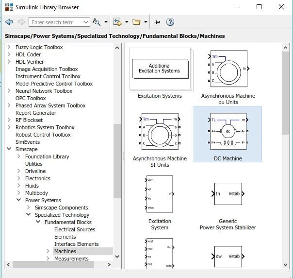
Figure 1: DC motor block
And the other method to implement DC motor is to construct it using gain and sum blocks. In this tutorial we will implement the later method. Now lets jump to the implementation portion. From the library browser first of all place the input block named as step. Select sources and then select step block and add it to the model as shown in the figure below,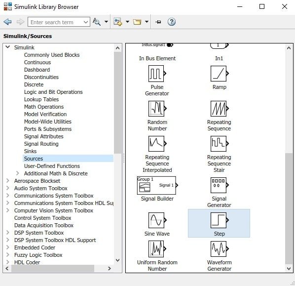
Figure 2: Step block
Now we will need a sum block, to add the feedback of the motor to the main input. In the library browser go to the sub block named Math operations and select the sum block and add it to model as shown in the figure below,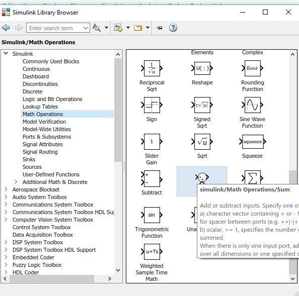
Figure 3: Sum block
In the same math operation subsection select the gain block and also add it to the model as shown in the figure below,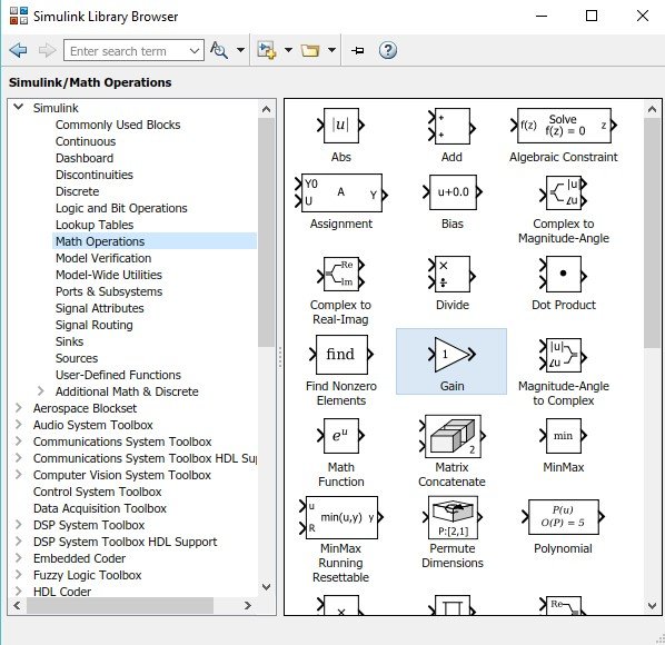
Figure 4: Gain block
We will be needing multiple sum and gain block so remember the path for future placement of these blocks. Now from the commonly used blocks section, select and add the block named integral to the model as shown in the figure below,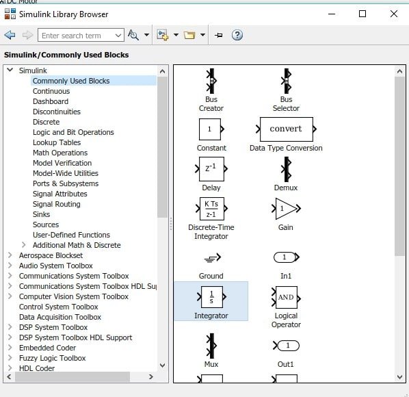
Figure 5: Integral block
Also we need to display the output of the motor on some oscilloscope. To make it easier select a scope for the sinks subsection of the library browser and add it to the model as shown in the figure below,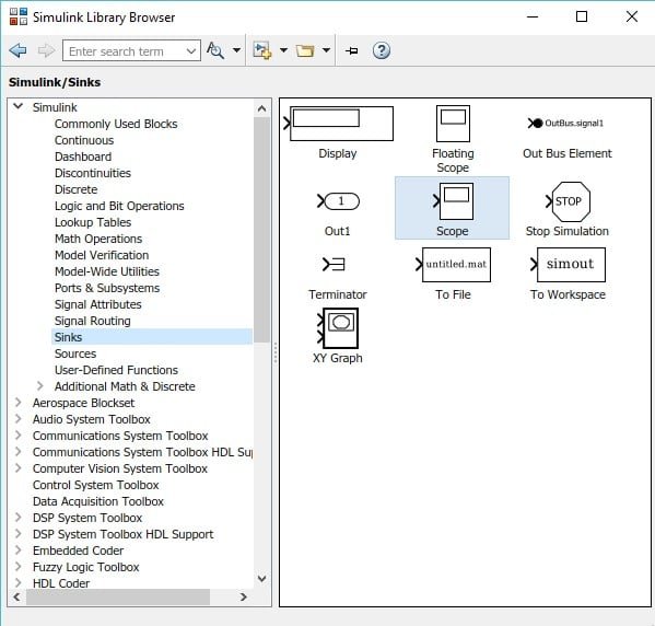
Figure 6: Scope block
Here we are done with adding blocks to the model we will now move towards designing the block diagram. At the input side place the step input block and a sum block. Double click on the sum block to change its number of inputs and update it to +– as shown in the figure below,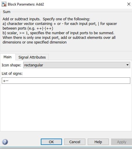
Figure 7: parameters of sum block
At the sum terminal of the sum block connect the input step and at one of the subtract terminal connect on gain block as shown in the figure below,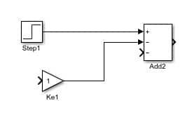
Figure 8: Input blocks
In the parameters block of this gain block write Ra in place of gain (which we will update later) as shown in the figure below,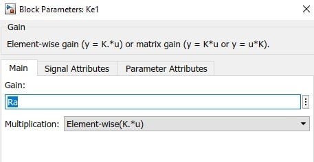
Figure 9: gain parameter
At the output of sum block connect another gain block and change its gain to 1/L (inductance) as shown in the figure below,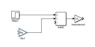
Figure 10: Inductance
At the output of this gain block connect an integral block, the output of which will be connected to another gain block and also to the input of Ra gain block as shown in the figure below,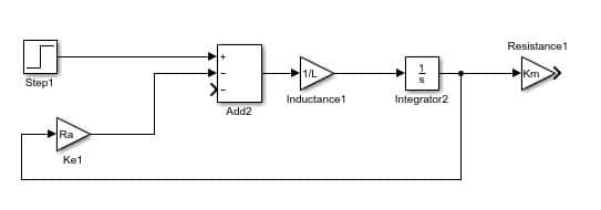
Figure 11: 1st stage
This will end the 1st stage and now we will design the second stage which will be same as the first stage instead the output from the integral of the second stage will be sent back to the subtract terminal in the sum block of 1st stage through a gain block. At the output of Km gain block connect a sum block with 2 input terminals (one + and one -) the output of which is connected to another gain block 1/J the output of which is connected to integra block whoes output will be provided to both the sum blocks as feedback as shown in the figure below,
Figure 12: Block diagram
Connect a scope at the output of the second integral block as shown in the figure below,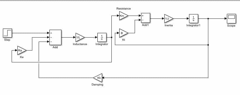
Figure 13: Complete diagram
Now we need to set the parameters of the gain block according to our need. In this example I will set the parameters as shown in the figure below,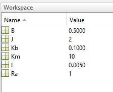
Figure 14: Parameters
Now run the model and double click on the scope to see the output. The output of the motor is critically damped which we can adjust by changing the gain Kb according to our need. The output of the motor is shown in the figure below,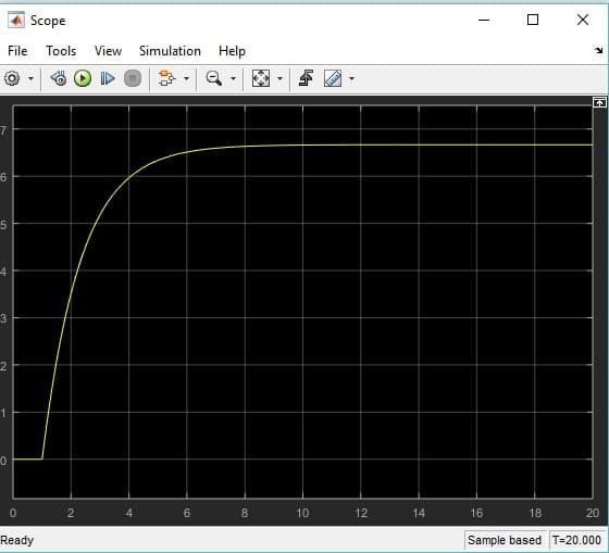
Figure 15: Output
Design and Simulate Dc Motor Using Matlab Simulink
Source: https://microcontrollerslab.com/dc-motor-implementation-simulink-matlab/
0 Response to "Design and Simulate Dc Motor Using Matlab Simulink"
Post a Comment